Ever wondered how capacitors store energy or why they're crucial in electronic circuits? Understanding capacitance is key for any electronics enthusiast or professional.
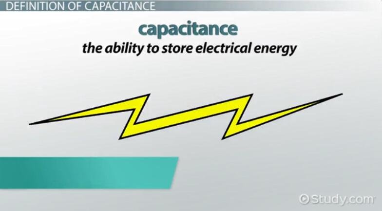
Capacitance, the ability of a capacitor to store charge, is crucial in electronics. Imagine a container that holds water. That's kind of like a capacitor holding electrical charge. Capacitance is simply how much charge a thing can store at a certain voltage. Think of it as the "size" of that water container. Bigger capacitance? More charge held. It's measured in Farads. Basically, it's the ability to store electrical energy in an electric field.
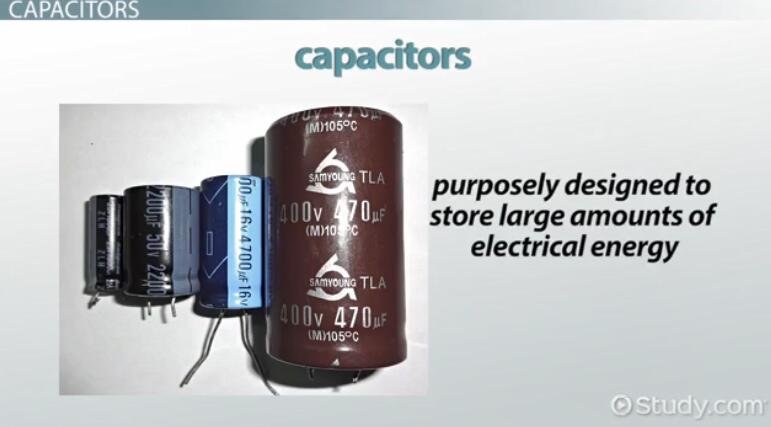
Capacitors are super useful! In circuits, they smooth out voltage, like a water filter. They can also block DC signals, letting AC pass. Think of them as timing devices too. They're key for making oscillators and filters.
For fixing stuff, knowing capacitance helps a lot. If a circuit's acting weird, a faulty capacitor is often the culprit. Checking their values with an oscilloscope multimeter can pinpoint problems. Replacing a bad one can bring a circuit back to life! Accurate measurement ensures optimal circuit performance.
This blog will explores how to measure capacitance using an oscilloscope multimeter, highlight its dual functionality for precision and diagnostics. After you read it, we hope you will have a basic understanding of how to measure capacitance.
Why Use an Oscilloscope Multimeter?
A regular multimeter gives you a single capacitance value. An oscilloscope multimeter, or "scope meter," shows how capacitance changes over time. You get a waveform, a visual representation. This is crucial for dynamic circuits.
Think of it like this: A regular meter says, "The water tank holds X gallons." A scope meter shows you how quickly the tank fills and empties.
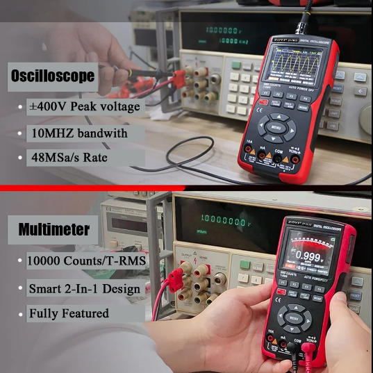
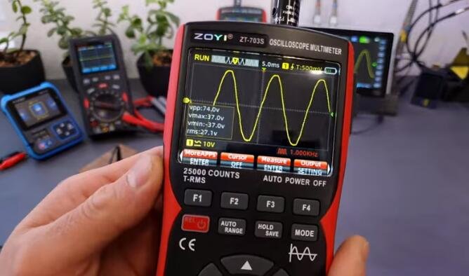
Il nostro ZOYI ZT-703S oscilloscope multimeter combines a digital multimeter (DMM) with an oscilloscope, offering both direct capacitance readings and waveform analysis. This dual approach provides not only capacitance values but also insights into capacitor health, such as leakage or ESR issues. It’s better for measuring capacitance because:
- See behavior over time: Watch the capacitor charge/discharge visually(unlike basic meters that just spit out a number).
- Spot hidden issues: Catch problems like leakage(slow charge loss) or ESR (inefficiency, like "electrical friction") that basic meters miss. (Source: All About Circuits, 2021)
- Test in-circuit: Often, you don’t need to remove the capacitor—saves time!
New terms:
- ESR (Equivalent Series Resistance): Hidden resistance inside a capacitor that wastes energy.
- Leakage: When charge "slips away" even when the capacitor should hold it.
This is especially useful when:
- You're dealing with AC signals.
- You need to see how a capacitor reacts to changing voltages.
- You want to detect subtle changes in capacitance, like those caused by temperature or frequency.
While multimeters offer a direct capacitance measurement, oscilloscopes provide a more dynamic and in-depth view. An oscilloscopes multimeter lets you see the behavior of the capacitance, not just its static value. This is highly beneficial for advanced troubleshooting and design. Here take ZOYI ZT-703S oscilloscope multimeter as an example to explore how to use both function effectively
Method 1: Direct Measurement Using Multimeter Mode
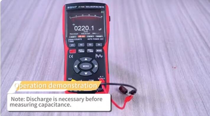
Before any measurement, especially capacitance, you must discharge the capacitor.
Why? Capacitors store electrical charge. Even after a circuit is powered off, a capacitor can hold a dangerous voltage. Touching a charged capacitor can give you a nasty, or even fatal, shock.
- Discharge before you measure.
How? Use a resistor to slowly bleed off the charge. Or, if you know what you are doing, a dedicated capacitor discharge tool. Never use a screwdriver directly across the capacitor terminals, it can cause a spark, damage the capacitor and even cause injury.
Think of it like this: a loaded spring. You wouldn't dismantle it without releasing the tension, right? Same with capacitors. So discharge them before you touch them.
- Step-by-Step Guide
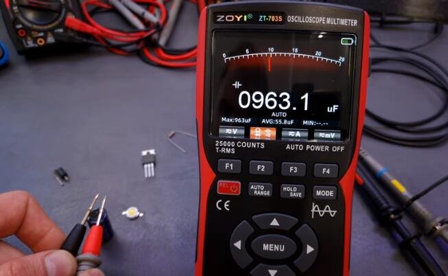
- Press Mode button to enter Multimeter working mode.
- Insert the black probe into the COM terminal and the red probe into the VΩHz terminal.
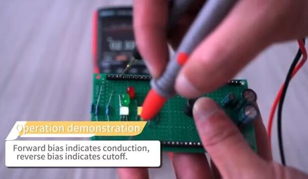
- In the diode mode, press the F2 key once to enter the capacitance mode.
- Connect the red probe to the positive terminal of the capacitor and the black probe to the negative terminal of the capacitor.
- Once the reading stabilizes, read the capacitance value displayed on the screen.
Capacitors aren't perfect. They have tolerances, meaning their actual capacitance can vary from the labeled value. Think of it like buying a bag of sugar: it says 1kg, but it might be a little more or less.
Capacitors have tolerance ratings, often expressed as a percentage (e.g., ±10%, ±20%). So, a 100µF capacitor with a ±10% tolerance could actually measure anywhere between 90µF and 110µF.
When you use a multimeter to measure capacitance, the reading you get might not be exactly what's printed on the capacitor. That's perfectly normal, as long as it falls within the tolerance range.
Here's why this matters:
- Circuit performance: In some circuits, precise capacitance is crucial. In others, a little variation is acceptable.
- Risoluzione dei problemi: Knowing the tolerance helps you decide if a capacitor is faulty. A reading outside the tolerance range suggests a problem.
- Component selection: When designing circuits, you need to choose capacitors with tolerances that meet your requirements.
Basically, a multimeter gives you a snapshot, and the tolerance tells you how much that snapshot can vary. So if you see a reading that is not exactly what is printed on the capacitor, do not automatically assume that the capacitor is faulty. Check the tolerance rating first.
Advantages:
Using a multimeter's capacitance mode is handy for quick checks. Here's a rundown of the advantages:
- Simplicity: It's easy to use, even for beginners.
- Portability: Multimeters are small and portable.
- Quick readings: You get a capacitance value quickly.
- Basic troubleshooting: It's great for identifying obviously faulty capacitors.
- Affordability: Most multimeters include capacitance measurement.
- Convenience: It is a function that is readily available on most multimeters.
While multimeter capacitance mode is useful, it has limitations:
- Static Values: It only gives you a single capacitance value. It doesn't show how capacitance changes over time or with frequency.
- Limited Accuracy: Readings can be affected by stray capacitance and component tolerances.
- Low-Value Limitations: Multimeters struggle with very small capacitances.
- In-Circuit Measurement Issues: Measuring capacitors while they're still in a circuit can give inaccurate readings due to other components. 1
- No Dynamic Behavior: You can't see how a capacitor reacts to changing signals, like AC voltages.
- Frequency Dependence: Capacitance can vary with frequency, which a standard multimeter won't show.
Method 2: Oscilloscope RC Time Constant Method
Using multimeter mode gives you a simple number, like "10µF." That's fine for basic checks. But what if you want to see how that capacitance behaves? That's where an oscilloscope shines.
Imagine a capacitor in an AC circuit. Its behavior changes with frequency. A multimeter won't show you that. By using oscilloscope mode, however, displays the voltage and current waveforms. You can see the phase shift, how the capacitor reacts to varying frequencies, and even detect subtle anomalies.
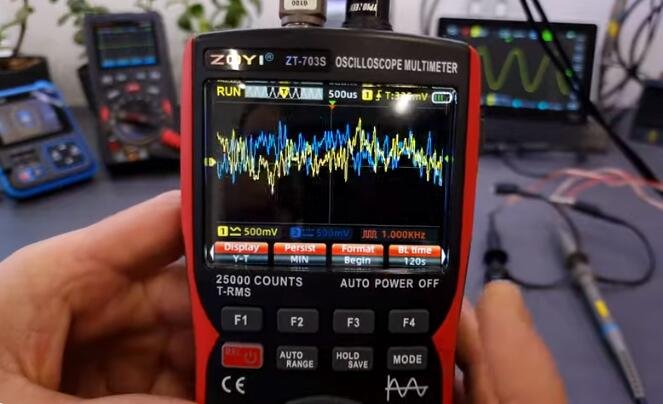
In oscilloscope mode really shines when it comes to analyzing a capacitor's charging and discharging characteristics. It's like watching a movie of the capacitor's behavior.
Here's how:
- Waveform Visualization: You can see the actual voltage curve as the capacitor charges and discharges. This curve tells you a lot about the capacitor's health and how it interacts with the rest of the circuit.
- Time Constant Measurement: The oscilloscope allows you to measure the time it takes for the capacitor to charge or discharge to a certain voltage level. This is called the time constant (RC). This is very important for timing circuits.
- Non-Ideal Behavior: Real-world capacitors aren't perfect. They have internal resistance and other imperfections. An oscilloscope can reveal these non-ideal behaviors, like leakage current or equivalent series resistance (ESR), that a simple multimeter wouldn't catch.
- Pulse Response: You can see how a capacitor responds to pulse signals, which is crucial in digital circuits. You can check for overshoot, undershoot, and ringing.
- AC Behavior: You can observe the phase shift between voltage and current in an AC circuit. This is fundamental to understanding how capacitors work in filters and other AC applications.
In oscilloscope mode lets you see the dynamics of charging and discharging, providing a much deeper understanding of the capacitor's performance than a static measurement could ever offer.
- RC Time Constant Method
let's dive into the RC time constant method for measuring capacitance using an oscilloscope. This method relies on the relationship between resistance (R), capacitance (C), and the time it takes for a capacitor to charge or discharge.
What is the RC Time Constant?
The RC time constant (τ, tau) is the time it takes for the voltage across a capacitor to reach approximately 63.2% of its final value during charging, or to drop to 36.8% of its initial value during discharging. It's calculated as: τ = R * C
Step-by-Step Procedure:
- Set Up the Circuit:
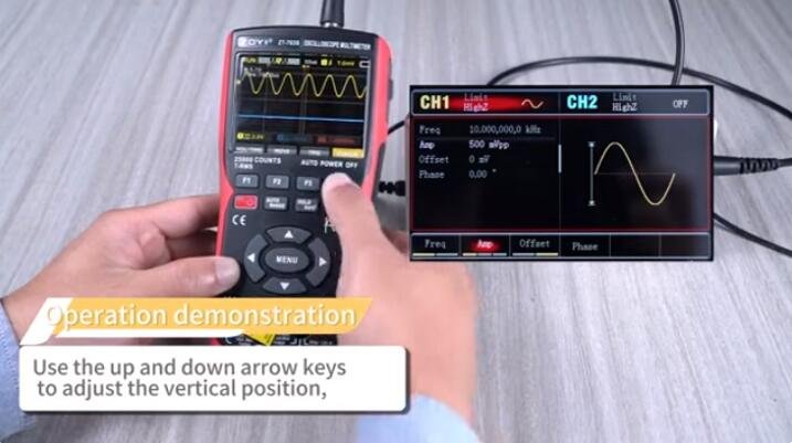
- You'll need a known resistor (R), the capacitor you want to measure (C), a square wave generator (from your oscilloscope or a separate function generator), and the oscilloscope itself.
- Connect the resistor and capacitor in series.
- Apply the square wave signal across the RC circuit.
- Connect the oscilloscope probe across the capacitor.
- Adjust the Oscilloscope: Set the oscilloscope to display the voltage waveform across the capacitor. Adjust the time base and voltage scale to clearly see the charging and discharging curves. Set the trigger so that the rising and falling edges of the square wave are stable.
- Measure the Time Constant (τ):
During the charging phase, observe the rising voltage curve across the capacitor.
Measure the time it takes for the voltage to reach 63.2% of the square wave's amplitude.
- During the discharging phase, observe the falling voltage curve across the capacitor.
- Measure the time it takes for the voltage to reach 36.8% of the square wave's amplitude.
- These measured times are the RC time constant (τ).
- Calculate Capacitance (C):
Once you have the measured time constant (τ) and the known resistance (R), you can calculate the capacitance (C) using the formula: C = τ / R
Considerazioni importanti:
- Accuracy of the Resistor: The accuracy of your capacitance measurement depends on the accuracy of the resistor. Use a precision resistor for best results.
- Square Wave Quality: The square wave generator should produce a clean, stable square wave.
- Stray Capacitance: Stray capacitance in the circuit and oscilloscope probes can affect the measurement, especially for small capacitance values.
- Discharging: Always discharge the capacitor before and after the measurement to ensure safety.
This method gives you a practical way to determine capacitance using oscilloscope mode, especially when a dedicated capacitance meter isn't available or when you need to analyze the dynamic behavior of the capacitor.
Measuring capacitance using an oscilloscope offers several distinct advantages, particularly in terms of precision, versatility, and diagnostic capability. Here's a concise summary of the key benefits:
- Dynamic analysis of capacitor behavior.
- Ability to measure capacitance in-circuit (with limitations).
- Visual representation of charging and discharging characteristics.
- Ability to see how a capacitor reacts to different frequencies
These advantages make oscilloscope-based capacitance measurement particularly valuable for troubleshooting, educational purposes, and applications requiring detailed component characterization.
While using an oscilloscope to measure capacitance offers valuable insights, it also comes with certain limitations. Here's a summary of those constraints:
- Requires more setup and knowledge than using a multimeter.
- Indirect measurement, requiring calculations.
While an oscilloscope provides a powerful tool for analyzing capacitor behavior, it's essential to be aware of its limitations and to take appropriate precautions to minimize errors.
Practical Applications & Troubleshooting
Let's get practical about measuring capacitance. You'll find it useful in a bunch of situations.
Practical Applications:
- Checking Capacitor Health: Is that old capacitor still good? A quick measurement can tell you. Especially useful in old electronics repair.
- Circuit Troubleshooting: If a circuit's acting weird, a faulty capacitor could be the culprit. Knowing the correct capacitance helps you pinpoint the problem.
- Filter Design: Capacitors are essential in filters. Measuring them ensures your filter works as intended, such as audio equipment, or power supplies.
- Component Matching: Sometimes, you need capacitors with precise values. Measuring helps you match them. This is very helpful in high precision analog circuits.
- Parasitic Capacitance Detection: Finding unwanted capacitance in circuits, especially important in high speed digital circuits.
Troubleshooting Tips:
- Start with a Multimeter: For a quick check, a multimeter with a capacitance function is your friend, which is simple and easy for basic checks.
- Oscilloscope for Deeper Dive: If you need to see how a capacitor behaves at different frequencies, grab an oscilloscope. This is where you see the "personality" of the capacitor.
- Check for Shorts and Opens: Before measuring, make sure the capacitor isn't shorted or open. A simple continuity test can save you headaches.
- Discharge Before Measuring: Always discharge capacitors before measuring them, especially high-voltage ones. Safety first! This prevents damage to your meter, and to you.
- Consider Lead Length: Short leads are better. Long leads add inductance, messing with your measurements. Especially true for small value capacitors.
- Temperature Effects: Capacitance can change with temperature. If you need a precise measurement, keep the components at a stable temperature.
Conclusione
An oscilloscope multimeter is indispensable for both hobbyists and professionals, offering precise capacitance measurements and diagnostic insights. By leveraging its dual capabilities, you ensure robust circuit performance and longevity.
ZOYI ZT-703S Oscilloscopio multimetro is a marvel of technology, blending innovation and versatility, witch seamlessly between DMM and oscilloscope. With waveform analysis, which diagnose capacitor health beyond mere capacitance. Explore our oscilloscope multimeter’s more features today for advanced electrical troubleshooting!
Have questions about how to measure capacitance in your projects? Contact our team for expert advice on choosing the right tool for your needs!